Edition 2025
The new version brings a change in the way each version is named. Like other Fine products, the versions will be named according to the year for which they are intended. The next version 2026 is planned for November 2025.
Cloud license management
Version 2025 brings a new way to manage licenses and protect the program. It is no longer necessary to use hardware keys to run programs. After purchase or renewal, the program license is placed on a cloud server where the programs control it. The license can also be downloaded for offline use, either to a computer or to a hardware key.
64-bit version
The program is compiled as a 64-bit application by default. This allows, for example, better use of the computer's operating memory. The 32-bit version is still available, but it must be selected manually in the installer.
Multi-threaded analysis in Truss 3D
The automatic truss design in "Truss 3D" is now run in multiple threads. As a result, the design time for the entire structure has been significantly reduced. The speed-up is particularly significant for multi-core processors.
National Annexes for Hungary and Romania
National annexes for Hungary and Romania have been added.
Fastener database
A fastener database has been added to the "Catalogues" section. This is a list of available nails and screws that are used in the design of the various structural details of the trusses. The fasteners are currently used in the design of perforated plates and T-braces. The database of fasteners can be transferred between computers as part of the "Company Catalogue".
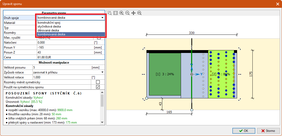
Combi and gusset plates
Support for combi and gusset (perforated) plates has been added to the program.
These boards are used to connect the production parts on site. The plates can be pressed into one production part at the factory and transported to the site. The connection to the second production part can then be made after transport using convex nails. With regard to the arrangement of the nails and holes, the combi plates should be used to join a maximum of two production parts at a perpendicular joint.
Gusset plates are also used to connect production parts on site, but all parts in the joint are connected by fasteners (nails, screws). Types BV/DS 03-01, BV/DS 03-07 and BV/DS 03-08 are available.
The design of fasteners in joints is based on EN 1995-1-1, chapter 8.2. The load capacity of the combi plates is assessed in the same way as that of the nail plates, since the part with nails shows significantly greater weakening. The load capacity of perforated plates is assessed in accordance with chapter 6.2 of EN 1993-1-1.
The range of combined and gusset plates can be modified in the properties of the "Nail plate supplier". New types of plates can be set for any joint in the "Connection type" drop-down list in the "Edit joint" window. The program automatically suggests the number of fasteners so that the joint is able to transfer the forces in the joint. The calculation uses the fastener that is selected in the "Nail plates" section of the "Project/truss settings" window. The program automatically suggests the number of fasteners and their placement. If the length of the fastener exceeds the limit for a double shear connection, the connection is designed as a single shear connection.
 Changing plate type
Enhanced roofing solver
Roofing solver supports also roofs with different eaves levels and multiple pitches above each other.
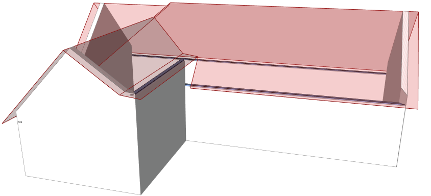 Roof created with the help of the new roofing solver
T-braces
In addition to traditional longitudinal bracing, T-braces are a new way to prevent the infill members (webs and verticals) from out of the plane buckling. They consist of a timber member that is fixed along the braced member. However, the cross-section of the brace is perpendicular to the cross-section of the braced member and the resulting cross-section is in the form of the letter T. As the T-bracing is connected only to a single member, it is a suitable method of bracing in places where the webbings of the individual trusses differ and where longitudinal bracing cannot be properly carried out. These locations are, for example, hips.
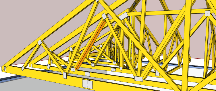 T-brace in a hip
The principle of the T-bracing design is based on chapter 9.2.5.2 of EN 1995-1-1. The T-bracing replaces the longitudinal bracing and is therefore attached to the braced member at locations where the program would place the longitudinal bracing to reduce the buckling length. This is usually the centre of the web or vertical. These connections transfer bracing forces to the brace. The T-bracing is further connected to the braced member at its beginning and end. These connections transfer the transverse forces to the stiffened planes of the upper and lower chords. In the assessment of the T-bracing, the overall stiffness of the brace and the ability of the fasteners to transfer the bracing forces are checked.
The T-braces can be specified in the "Member properties" in the "Buckling" tab by setting "Replace longitudinal braces by T-braces". It is possible to choose the type of fastener to be used for the T-braces. The other parameters (fastener size and cross-section of the longitudinal brace) can be designed automatically by the program or entered manually.
T-braces can also be included in cutting lists and exports for CNC saws. In this case, the "Document T-braces" setting must be checked in the "Application Options" in the "Documentation" tab.
Inserting multiple drawings
A new "Block" tool has been created in the "Drawing" toolbar, replacing the "Construction layer" toolbar from previous versions. With this change, it is possible to insert multiple drawings into a project and take advantage of the wide range of available manipulations (move, copy, rotate, mirror, scale) available for all objects from this toolbar. Blocks are inserted into the active layer. Thus, the further behaviour of the block can be influenced by the layer properties (off/on, lock, print).
 Blocks used in the roof plan
If the block is large and contains parts that are unnecessary for further work, it is possible to clip the block. To do this, use the "Add Clip" command that appears in the "Properties" sidebar if the block is selected on the workspace.
In the current version, if an older project with construction layer is opened, the program will automatically convert it to a block in the newly created layer.
Basic IFC file import
In addition to the *.dwg, *.dxf and *.dgn formats, it is also possible to insert documents in *.ifc format using the "Block" tool. If this format is used, a projection from the solid model into a floor plan is created, which can be used for structure input.
Inserting images and PDFs
The second new tool in the "Drawing" bar is "Image". It is used to insert raster or vector images in various formats, including *.pdf document. The image can be used, for example, to add a structure view into a drawing or as an approximate basis for entering a structure.
 Image used as a basis for a structure input
The tool first opens a window in which the image can be loaded either from a file or from the Windows clipboard. The image can then be cropped, rotated, mirrored, and possibly adjusted for brightness or contrast. After pasting the image to the desktop, it is necessary to enter the size of the image with the cursor.
If the image is selected, in the "Properties" sidebar it is possible to adjust the position of the image relative to the insertion point, its rotation and opacity. This can be used especially in cases where the image is used as a background and the walls and other parts of the structure need to be seen. This is because on a 2D workspace, images are drawn like other drawing objects over the structure itself.
Enhanced editing features
The editing functions "Scale" and "Rotate" now also have the option of entering a reference scale or angle. To use this option, you must enter the letter "r" on the keyboard after entering the origin of the magnification or the centre of rotation. Help for this procedure is displayed directly at the mouse cursor. These new options are particularly useful in situations where it is not possible to find the exact numerical value of the transformation. Examples include adjusting the scale or rotating a scanned drawing.
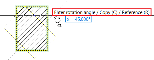 Extended options for "Rotation" tool
Option to specify two extended top chords at one end of the truss
Option to specify two extended top chords at one end of the truss. It is now possible to specify two different extended top chords at both ends of the truss location. This can cover, for example, cases where it is necessary to extend a rafter of a hip truss to the girder and to the hip rafter.
Choice of language
Each user has the option to choose the language of the application. The following languages are available: Czech, Slovak, English, German, French, Polish. The default language of the application can be changed in the "Language and environment" window, which can be launched from the "Tools" - "Default settings" section of the main menu. The colour mode selection has also been moved to this window.
The output language is now selected directly in the main toolbar of the print window.
Option to select a different use for the nail plate
For each nail plate (also gusset and combi plates) it is possible to select a different maximum utilization than that used in the rest of the truss. The utilization is entered in the plate editing window.
Default support properties for truss-truss connections
The "Supports" section of the "Project settings" window in the default settings contain the option to specify the default support properties that will be created in a truss to truss connection. Until now, the program inserted theoretical support in these places, which did not correspond to the actual conditions in that connection. By specifying the width of the support, a more realistic structural model can be created.
The default support width is selected to be 100mm.
Option to specify in-plane buckling length of the member
In the "Buckling" tab of the member properties, it is possible to enter a custom value of the in-plane buckling and thus overwrite the buckling lengths obtained on the topology basis. This function can be used especially in cases where the buckling length is greater than the member length (segments of arch structures, etc.). It can also be used in the case of compression members that are stabilized by a parallel tension member connected by nail plates.
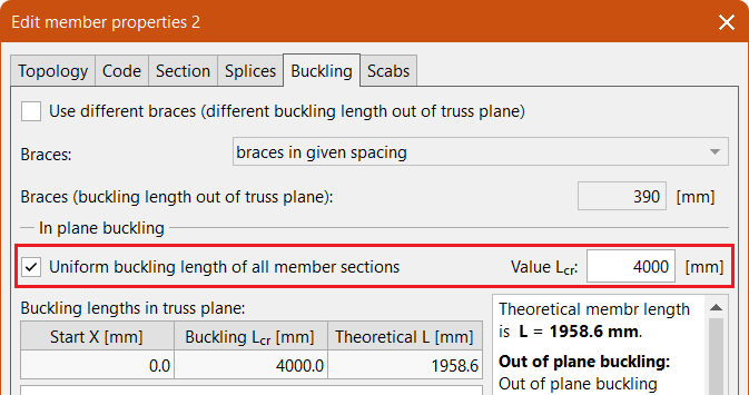 Custom value of the in-plane buckling length
Choice of consequence class
For the design standard "EN 1995-1-1", it is possible to select the "Consequence class" in the "Standard" part of the "Project/Truss settings". This setting can be used to take into account the reliability of the structure according to Annex B of EN 1990.
Option to delete selected drawing objects
In the context menu of the workspace, a new item "Delete selected drawing objects" has been added to delete selected drawing objects (construction lines, manually entered dimensions, etc.). This item will only appear in the menu if at least one of these objects is selected. This function is available in both "Truss 3D" and "Truss 2D".
Forces in general connections according to load duration
The forces in general connections, which are available in the document "Structural analysis", can now be divided according to the load duration. The new switch "By load duration" in the tree menu of the structural analysis document is used for this purpose. If this setting is used, the program lists the maximum design forces and moments separately for each load duration that occurs in the project. Both the listing for production parts and the listing for parts can be divided by the load duration.
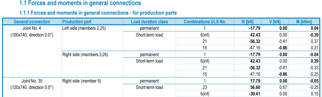 Forces in general connections based on the load duration
Option to turn on/off the load in the "Results" section
In "Truss 2D" in the "Results" section, the setting "Draw loads for load cases" can be used to show or hide the load drawing for load cases. The loads are drawn as they enter the structural analysis. This means, for example, that the area load is already multiplied by the loading width and the resulting value therefore represents the load per linear meter.
Shortcut for zoom to fit all
The "Home" keyboard shortcut can now also be used to enlarge the structure to view the whole.
Export JSON
It is possible to export a *.json file from the program. It can be used to link to other applications.